
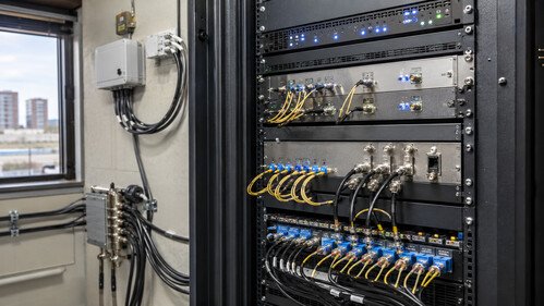
Local CATV channel insertion with RF over Fiber combines the reach and reliability of optical transport with the flexibility of site-specific programming. By converting the central service package back to RF and carefully combining it with locally modulated channels, operators can create customized lineups without duplicating the entire headend infrastructure. The key to dependable performance is disciplined RF engineering: correct frequency planning, balanced carrier levels, adequate filtering and isolation, high-quality 75-ohm components, and measurements throughout the distribution network.
Cable television networks often need to distribute a common package of television and data services while also delivering content intended only for a particular building, campus, hotel, hospital, or residential area. Local CATV channel insertion makes this possible by combining locally generated RF channels with the main broadband signal. When RF over Fiber (RFoF) technology is used for transport, the solution can cover long distances with low loss and strong immunity to electromagnetic interference.
How RF over Fiber Works
In an RFoF system, a broadband CATV signal modulates an optical transmitter. The resulting optical signal travels through fiber to a remote location, where an optical receiver converts it back into an electrical RF signal.
Unlike coaxial cable, optical fiber introduces very little attenuation over long distances. It also provides electrical isolation between sites and is not affected by ground loops, lightning-induced interference, or nearby electrical equipment. These characteristics make RFoF particularly suitable for large campuses, multi-building properties, metropolitan networks, and other distributed installations.
Typical CATV RFoF links can transport analog television, digital QAM channels, FM radio, and other RF services over a wide frequency range. The exact bandwidth depends on the transmitter, receiver, and network design.
The Local Channel Insertion Process
Local insertion normally takes place after the optical signal has been converted back to RF. The output of the optical receiver contains the main CATV channel lineup. A locally generated channel is then added through an RF combiner.
The local content may come from a digital signage player, security camera system, hotel information service, campus studio, satellite receiver, or another video source. If the source does not already produce a CATV-compatible RF signal, it must first pass through an encoder and modulator. The modulator places the content on a selected analog or digital channel.
A simplified installation includes:
1. An optical transmitter at the central headend.
2. A fiber-optic link to the remote site.
3. An optical receiver that restores the broadband RF signal.
4. A local encoder or modulator.
5. Attenuators, filters, or amplifiers for signal conditioning.
6. An RF combiner that merges the main and local signals.
7. A coaxial distribution network serving local subscribers.
The inserted channel must occupy an unused frequency in the incoming lineup. Alternatively, an existing channel can be removed with a notch filter and replaced by the local service.
Signal-Level Management
Correct level adjustment is one of the most important parts of local channel insertion. The locally generated carrier should have approximately the same level as neighboring channels. If it is too weak, receivers may experience noise, pixelation, or loss of service. If it is too strong, it can overload amplifiers and create interference across the network.
The total composite power must also be considered. Adding channels increases the combined RF power presented to downstream amplifiers. Excessive input power can produce nonlinear distortion, including composite triple beat and composite second-order distortion. In digital networks, poor level management may reduce the modulation error ratio and increase the bit error rate.
Installers should measure the signal at the optical receiver output, local modulator output, combiner output, and representative subscriber outlets. A spectrum analyzer or CATV signal-level meter is normally used to verify channel power, frequency accuracy, carrier quality, and unwanted emissions.
Filtering and Isolation
RF combiners should provide sufficient isolation between their input ports. Without adequate isolation, the local modulator may feed energy back toward the optical receiver, while the broadband CATV signal may enter and disrupt the local equipment.
Filters can improve system performance. A band-pass filter limits the local modulator output to the intended channel, while a notch filter removes an existing carrier from the main feed. Properly selected filters help prevent overlapping channels, adjacent-channel interference, and broadband noise.
All unused RF ports should be terminated with the correct impedance, usually 75 ohms. Connectors, splitters, amplifiers, and cables must also maintain this impedance to minimize reflections and preserve signal quality.
Benefits of RFoF-Based Local Insertion
The main advantage of this architecture is flexibility. A central headend can deliver a standard service package to many remote sites, while each site inserts its own content independently. There is no need to create a separate optical feed for every local channel lineup.
Other benefits include:
- Long transmission distances with low signal loss.
- Reduced use of coaxial trunk amplifiers.
- Immunity to electromagnetic interference.
- Electrical isolation between buildings.
- Centralized management of common programming.
- Easy customization of services at remote locations.
- Support for both analog and digital RF formats.
Design Considerations
A successful installation begins with a complete frequency plan and RF power budget. Engineers should confirm the available channel frequencies, RFoF link bandwidth, optical power range, receiver output level, combiner loss, amplifier capacity, and required signal level at each outlet.
For digital QAM services, channel power alone is not enough. Modulation error ratio and bit error rate should also be checked. Where regulatory requirements apply, leakage, shielding, and permitted signal levels must be verified.